Given the name of this blog and the number of requests that I’ve had, I think it’s high time we discussed serial ports; specifically, serial ports in embedded systems.
My goal here is to describe the techniques that I’ve found effective in identifying and reverse engineering embedded serial ports through the use of definitive testing and educated guesses, and without the need for expensive equipment.
Introduction
Serial ports are extremely useful to embedded developers, who commonly use them for:
- Accessing the boot loader
- Observing boot and debug messages
- Interacting with the system via a shell
Needless to say, this functionality is also useful to hackers, so finding a serial port on an embedded device can be very advantageous. As a case study, we’ll be examining the PCB of a Westell 9100EM FiOS router for possible serial ports:

Westell 9100EM PCB
Now, these aren’t your dad’s RS-232 serial ports that we’re looking for; these are Universal Asynchronous Receiver Transmitters (UARTs), commonly found in embedded devices. Although protocol compatible, RS-232 and UART are not voltage compatible (from here on out I will use the terms “UART” and “serial port” interchangeably). UARTs most commonly operate at 3.3 volts, but can also be found operating at other standard voltages (5, 1.8, etc).
Unfortunately there aren’t any industry standardized UART pin outs, and manufacturers don’t often go around advertising or documenting their debug interfaces, so we’ll need to do a bit of work in order to interface with these serial ports. Specifically, we need to reverse engineer both the hardware interface and the software protocol settings.
Let’s start with the hardware interface first. For this, you’ll need a multimeter and a pair of eyeballs (or even one will do just fine). Yes, oscilloscopes and logic analyzers are useful and sometimes necessary, but 99% of the time a trusty multimeter and a bit of knowledge is all you need.
Identifying Serial Headers
The first step is to try to identify potential candidates for serial port headers. Most serial port headers have at a minimum four pins:
- Vcc
- Ground
- Transmit
- Receive
Typically you’ll want to look for a single row of 4-6 pins, although this is not a hard and fast rule and they can come in any pin configuration the manufacturer has decided on.
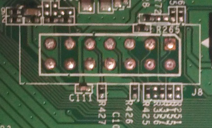
On our 9100EM PCB we find two possible candidates, labeled P1402 and P1404:

Possible serial port headers
Sometimes you won’t have a nicely broken out set of pins like this, and you’ll have to examine test points on the board; usually starting with test points closest to the SoC is a good idea. Here is an example of a serial port exposed via test points on a different board, the WL530G:

Serial port test points on a WL530G
In either case the process of pin identification is the same, but usually takes longer if there is no header since there will likely be more than 4 test points on the board that you will need to examine.
At this point either P1402 or P1404 could be serial port headers. Or they could both be serial port headers. Or neither could be a serial port header. So we’ll examine the pins on each header individually to try to gain some insight.
Visual Inspection
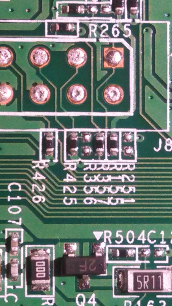
First, let’s visibly inspect the pins. We’ll start by taking a look at P1402:

P1402 top

P1402 bottom
On the top layer of the PCB the right most pin is labeled as pin “1″. This is not terribly important, but it gives a common frame of reference when describing the pin numbers.
On the bottom of the PCB we see that pin 3 has four traces in a crosshair pattern that connect it to the surrounding ground plane. This easily identifies pin 3 as ground.
Pins 2 and 4 have thin traces connected to them, while pin 1 is connected to a fatter trace. Wide traces are typically used for supplying power, while narrow traces are usually used for signal traces. This suggests that pin 1 is Vcc and pins 2 and 4 are potentially transmit and receive (although we don’t yet know which is which).
Let’s take a look at the P1404 header now:

P1404 top

P1404 bottom
Here, the left most pin is marked as pin 1. Again, we see that pin 3 is connected to ground on the bottom layer of the PCB. Pin 4 also has a thin trace connected to it, so it could be a transmit or receive pin.
The other two pins of P1404 however have no visible traces connected to them on either the top or bottom layers of the PCB. It could be that they aren’t connected to anything, but more likely their traces are connected on one of the inner layers of the PCB that we can’t see. Time to break out the multimeter.
Identifying Grounded Pins
A continuity test introduces a small current into the circuit; if enough current passes from one probe to the other (i.e., there is sufficiently little resistance), the multimeter will emit an audible tone indicating that the points that the probes are touching are electrically connected.
The first thing we want to do is perform a continuity test between ground and all the pins on each of the headers using the multimeter. This will tell us which pins are connected directly to ground. We’ll start with P1402.
Metal shielding is a convenient ground point to use for testing. Placing one probe on a shield and touching the other to pin 3, the multimeter emits a continuous audible tone, indicating that pin 3 is connected to ground as we previously observed:

Continuity test between pin 3 and ground
Performing the same test against pins 2 and 4 results in no audible tone, so we know those pins aren’t grounded.
The same continuity tests for P1404′s pins 2, 3 and 4 produce the same results. Thus we know that for both P1402 and P1404 pin 3 is grounded and pins 2 and 4 are not.
Identifying Vcc
Vcc is less important to identify since we don’t actually need to connect anything to it, but locating the Vcc pin is a good exercise and is useful in eliminating the Vcc pin as a possible candidate for transmit or receive.
Based on the trace widths, we suspect that pin 1 is Vcc; measuring the voltage on pin 1 when the board is powered on appears to confirm this:

Measuring voltage on P1402 pin 1

A steady voltage reading on P1402 pin 1
The same voltage readings hold true for P1404′s pin 1 as well, suggesting that both P1402 and P1404 have pin 1 tied to Vcc.
Another method of identifying Vcc is to perform a continuity test between ground and the suspected Vcc pin. Although it may first appear counter intuitive, this will commonly result in a very short beep (though not a continuous tone).
What happens with the Vcc continuity test is that there is usually a filter capacitor connected between the Vcc pin and ground. This is done to eliminate any possible noise in the power lines on the PCB, and such filter capacitors are used liberally in any well designed board. Due to the nature of how capacitors work, they will “pass” a direct current very briefly until they are charged to capacity, at which point they will cease “passing” direct current and will “block” direct current, resulting in the short beep observed during the continuity test (it is worth nothing that current doesn’t actually pass through a capacitor, although it appears that way to an outside observer).
Although it doesn’t always work, the continuity test is a more conclusive method of determining Vcc than simply measuring the voltage on each pin, as any number of pins could all read the same voltage. Note that you will also need a multimeter with a rather responsive continuity tester in order to perform this test properly; cheaper ones can take up to a second or more before they are triggered, at which point the capacitor has already been charged. Most multimeters in the $100 range should suffice.
Identifying the Transmit Pin
The transmit pin is fairly easy to identify provided that the serial port is active and is transmitting data (and if it’s not, this entire effort will likely be futile anyway). The transmit pin on the board will be pulled high to the same voltage as Vcc (typically 3.3 volts). As it transmits bits of data, the voltage will drop to 0 volts (to send a “space”), then back to 3.3 volts (to send a “mark”). When reading a changing DC voltage, digital multimeters will end up displaying an average of the sampled voltage; this means that the average voltage – and thus, the voltage displayed on the multimeter – will briefly dip down during bursts of activity on the transmit pin.
The most activity on the transmit pin typically occurs during system boot up when all the boot information from the bootloader/kernel/system is being printed to the serial port. By monitoring pins 2 and 4 during boot, we should be able to easily identify which of them is the transmit pin. Let’s try header P1402 first:

Measuring voltage on P1402 pin 2

Measuring voltage on P1402 pin 4
The voltage readings for both pins 2 and 4 on header P1402 are a steady 3.3 volts with no fluctuations:

Voltage reading for P1402 pins 2 and 4
This is not encouraging, so let’s move on to the P1404 header. We’ll start with pin 2:

Measuring voltage on P1404 pin 2
The voltage reading on pin 2 hovers around 40 millivolts for the first few seconds, then it jumps to a steady 2.3 volts:

Initial voltage reading for P1404 pin 2

Final voltage reading for P1404 pin 2
Let’s check pin 4 next:

Measuring voltage on P1404 pin 4
The voltage reading for pin 4 is a steady 3.3 volts for the first few seconds:

Initial voltage reading for P1404 pin 4
Then suddenly we begin seeing rapid but substantial changes to the voltage on pin 4:

P1404 pin 4 voltage dropping to 2.4 volts

P1404 pin 4 voltage rising back up to 3.2 volts

P1404 pin 4 voltage dropping back down to 2.3 volts
There is definitely some activity on P1404′s pin 4, indicating that it is in fact an active data pin and likely the transmit pin of a serial port.
Although this is an effective method of identifying the transmit pin, it is worth noting that if the serial port only transmits a small amount of data, the voltage fluctuations will be too brief for the multimeter to register and you will need an oscilloscope or logic analyzer to capture the data activity on the transmit pin. This is rare however; usually there is ample data sent out on the serial port for this method to work.
Identifying the Receive Pin
Definitively identifying the receive pin is the most difficult, as it has no truly unique defining characteristics. I have observed various voltages for the receive pin from one system to the next, including:
- Pulled high to the same voltage as Vcc
- Pulled high to a voltage a few hundred millivolts lower than that of Vcc
- Left “floating”, wildly fluctuating around a few hundred millivolts
- Left “floating” for a few seconds and then pulled high when the serial port is initialized
Since we have only one unknown pin left on both headers and we know that only P1404 is active, by process of elimination we can assume that pin 4 on P1404 is the receive pin. However, sometimes it just comes down to connecting a serial adapter to all possible receive pins individually, pressing a few keys in minicom (or your terminal emulator of choice) and seeing what happens. Speaking of connecting our serial adapter, let’s do just that.
Connecting a UART Adapter
Inexpensive USB to UART adapters are readily available and are supported by default on Linux – they just show up as a standard USB serial port and can be used with minicom, python, etc. We will need to connect our UART adapter to the serial port in the following manner:
- The adapter’s ground pin must be connected to the serial port’s ground pin
- The adapter’s transmit pin must be connected to the serial port’s receive pin
- The adapter’s receive pin must be connected to the serial port’s transmit pin
The easiest method of accomplishing this is to cut a breakaway header to size and solder it in to P1404:

Breakaway header soldered into place
And use some male-to-female jumpers to connect the appropriate pins between the serial port and the adapter:

UART adapter wired to P1404
Discovering the Baud Rate
With our hardware in place, we’re ready to start checking the serial port’s protocol settings. Serial ports can have a variety of settings, and we need to know all of them in order to communicate with the serial port:
- What is the baud rate?
- How many data bits are used?
- How many parity bits are used?
- How many stop bits are used?
Luckily, the de facto standard is to use 8 data bits, no parity bits and 1 stop bit (abbreviated as “8N1″), so that only leaves the baud rate unknown. Trial and error is the fastest and easiest method for identifying the baud rate. Since serial ports are typically used to display debug information (i.e., they transmit ASCII data), and there are only a small number of possible baud rates, it is practical to cycle through all possible baud rates until intelligible data is observed.
Or, at least that’s the way it works in theory. In practice all of the terminal emulation programs that I’ve used make it cumbersome to change the baud rate on the fly, if they even support doing so at all. To address this, I wrote a tool called baudrate that attempts to auto detect the baud rate of an actively transmitting serial port (you can also manually cycle through each baud rate if you prefer). Once finished, it saves out a minicom compatible configuration file and optionally fires up minicom for you.
With our UART adapter connected, let’s run baudrate (I’m using manual mode for demonstration purposes, but the auto-detection feature works like a charm here as well):
eve@eve:~$ sudo ./baudrate.py -p /dev/ttyUSB0

Starting baudrate detection on /dev/ttyUSB0, turn on your serial device now.
Press Ctl+C to quit.


@@@@@@@@@@@@@@@@@@@@@ Baudrate: 115200 @@@@@@@@@@@@@@@@@@@@@
We can change the baud rate to the next higher/lower baud rate by pressing the up/down arrow keys respectively:
@@@@@@@@@@@@@@@@@@@@@ Baudrate: 115200 @@@@@@@@@@@@@@@@@@@@@


@@@@@@@@@@@@@@@@@@@@@ Baudrate: 57600 @@@@@@@@@@@@@@@@@@@@@    <--- Down arrow decreases baud rate


@@@@@@@@@@@@@@@@@@@@@ Baudrate: 115200 @@@@@@@@@@@@@@@@@@@@@    <--- Up arrow increases baud rate
OK, now let’s turn on the 9100EM and see what happens:
@@@@@@@@@@@@@@@@@@@@@ Baudrate: 115200 @@@@@@@@@@@@@@@@@@@@@

Starting entry for CP1 @0xa3400000
memsize=52
CPU revision is: 00019641
Primary instruction cache 16kB, physically tagged, 4-way, linesize 32 bytes.
Primary data cache 16kB 4-way, linesize 32 bytes.
Linux version 2.4.21openrg-rmk1 #2 Thu Aug 28 19:30:48 CDT 2008
Determined physical RAM map:
User-defined physical RAM map:
 memory: 03400000 @ 00000000 (usable)
On node 0 totalpages: 13312
zone(0): 4096 pages.
zone(1): 9216 pages.
zone(2): 0 pages.
Kernel command line:  mem=52M
mips_counter_frequency:166666667
r4k_offset: 00196e6a(1666666)
Calibrating delay loop... 222.00 BogoMIPS
Memory: 44356k/53248k available (1568k kernel code, 8892k reserved, 6696k data, 4k init, 0k highmem)
Dentry cache hash table entries: 8192 (order: 4, 65536 bytes)
Inode cache hash table entries: 4096 (order: 3, 32768 bytes)
Mount cache hash table entries: 512 (order: 0, 4096 bytes)
Buffer-cache hash table entries: 1024 (order: 0, 4096 bytes)
Page-cache hash table entries: 16384 (order: 4, 65536 bytes)
Checking for 'wait' instruction...  unavailable.
POSIX conformance testing by UNIFIX
PCI: Probing PCI hardware on host bus 0.
Autoconfig PCI channel 0x801d19e0
Scanning bus 00, I/O 0x1ae00000:0x1b000001, Mem 0x18000000:0x1a000001
00:0e.0 Class 0200: 168c:001a (rev 01)
        Mem at 0x18000000 [size=0x10000]
Linux NET4.0 for Linux 2.4
Based upon Swansea University Computer Society NET3.039
Initializing RT netlink socket
Starting kswapd
...
It looks like the first baud rate we tried, 115200, is correct (this is not surprising as 115200 is one of the more common baud rates used in practice). Pressing Ctl+C we can stop the capture and save the settings to a minicom config file, in this case I just named it ’9100em’:
Detected baudrate: 115200

Save minicom configuration as: 9100em

Configuration saved. Run minicom now [n/Y]? n

eve@eve:~$
Getting a Shell
Now we can run minicom:
eve@eve:~$ minicom 9100em
And see what we get:
...
12/31 19:00:57 - Starting SoC reset sequence...
12/31 19:00:58 - Clink FS shared data area written
12/31 19:00:58 - CLNK_ETH_CTRL_RESET returned status 0 after 0.914 seconds
12/31 19:00:58 - FSUPDATE: Pass = 1, Tuned Freq = 1000 MHz (8)
12/31 19:01:10 - Clink Reset Cause :0x4 Reg:0x80240100 Dbg:0x0
12/31 19:01:10 - Starting SoC reset sequence...
12/31 19:01:11 - Clink FS shared data area written
12/31 19:01:11 - CLNK_ETH_CTRL_RESET returned status 0 after 0.903 seconds
12/31 19:01:12 - FSUPDATE: Pass = 1, Tuned Freq = 1150 MHz (14)

Username: admin
Password: *********

Wireless Broadband Router> help
Error: help should be called with at least 1 argument
help   Show help for commands within this menu

Usage:
        help all - show all available commands in the current level
        help [category]... category - show commands in a certain category
        help [category]... command - show detailed help for a specific command
        help -s string - search for categories/commands containing the string

Availble help Categories
help upnp - show help about UPnP commands
help conf - show help about Read and write Wireless Broadband Router configuration data
help option_manager - show help about Option Manager
help fireball - show help about Fireball configuration and control
help cwmp - show help about CWMP related commands
help bridge - show help about API for managing ethernet bridge
help firewall - show help about Control and display Firewall and NAT data
help connection - show help about API for managing connections
help inet_connection - show help about API for managing internet connections
help misc - show help about API for Wireless Broadband Router miscellaneous tasks
help firmware_update - show help about Firmware update commands
help log - show help about Contorols Wireless Broadband Router logging behaviour
help dev - show help about Device related commands
help kernel - show help about Kernel related commands
help system - show help about Commands to control Wireless Broadband Router execution
help flash - show help about Flash and loader related commands
help net - show help about Network related commands
help cmd - show help about Commands related to the Command module

Returned -1
Wireless Broadband Router> help system

Command Category system - Commands to control Wireless Broadband Router execution
die               Exit from Wireless Broadband Router and return ret
ps                Print Wireless Broadband Router's tasks
entity_close      Close an entity
etask_list_dump   Dump back trace of all etasks
restore_default   Restore default configuration
reboot            Reboot the system
ver               Display version information
print_config      Print compilation configuration. Search for option if specified
exec              Execute program
cat               Print file contents to console
shell             Spawn busybox shell in foreground
date              Print the current UTC and local time
exit              Exit sub menu
help              Show help for commands within this menu

Returned 0
Wireless Broadband Router>
Some serial ports require a login, others don’t. In this case the login was just the administrator user name and password for the device, which drops us to a custom command line shell with which we can manage the router. Based on the output from ‘help‘, the ‘system shell’ command should provide a root shell, which it does:
Wireless Broadband Router> system shell

BusyBox v1.01 (2005.09.07-07:38+0000) Built-in shell (lash)
Enter 'help' for a list of built-in commands.

/ # cat /proc/cpuinfo
system type             : TWINPASS-E
processor               : 0
cpu model               : unknown V4.1
BogoMIPS                : 222.00
wait instruction        : no
microsecond timers      : yes
tlb_entries             : 16
extra interrupt vector  : yes
hardware watchpoint     : yes
VCED exceptions         : not available
VCEI exceptions         : not available
/ #
Conclusion
That’s it! Using just a multimeter and some free software we have logically identified the serial port’s physical interface, discovered its baud rate and gotten a shell with which we can further interrogate the system.


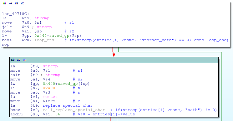
![replace_special_char(entries[i]->value);](http://www.devttys0.com/wp-content/uploads/2014/05/call_replace_special_char.png)
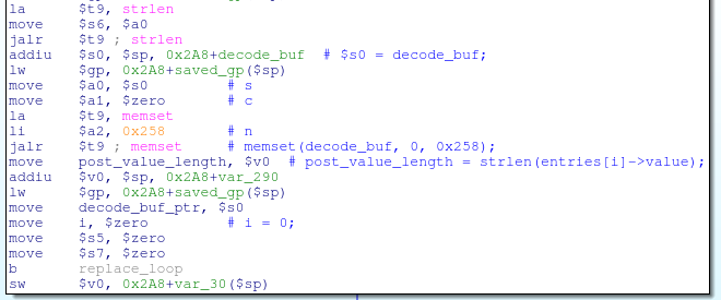

![decode_buf[j] = post_data[i];](http://www.devttys0.com/wp-content/uploads/2014/05/store_data_to_buf.png)


